This piece will discuss some general aspects of passenger vehicle design. There are several interacting parameters which need to be considered together.
The first of these is what is known as the static loading gauge. This can be thought of as the aperture through which all railway vehicles must be able to pass when running slowly on straight track. In practice, tracks are curved and railway vehicles cut across and project beyond the chord of a circle. Within the wheelbase, the distance cut across the curve is sometimes known as the overthrow and the projection beyond the wheelbase is referred to as the kick-out. A long vehicle cuts off more of a chord than a short one (diagram below) Taking curvature into consideration in this way leads to the concept of the dynamic loading gauge, which, however, also takes account of the suspension characteristics of the vehicle.
The diagram shows how gaps between the platform and the train will arise differently at concave and convex platform faces, and that these gaps can be minimised by keeping doorways as close as possible to bogie centres.

Following the nationalisation of Britain's railways in 1948, a survey of the infrastructure was made and an optimum loading gauge established for passenger vehicles. This was known as the C1 loading gauge and eventually it became possible for vehicles built to this gauge to operate over almost the entire system. The C1 loading gauge applied to vehicles of a nominal 20 metre width with bogies at 14.174 metre centres, of which the first were the Mark 1 fleet.
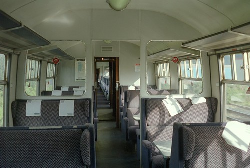
These (above) were characterised by curved bodysides with the width reducing to cantrail level (where the roof joins the bodyside)
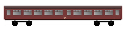
Vehicles to a similar length are still being built, but all of them have two pairs of bi-parting doors at the 1:3/2:3 position. (below)
This divides the vehicle into three saloons, one of four bays in the middle and two of two bays at each end. This is not a particularly satisfactory arrangement. If the vehicle is a monocoque construction, then the large door apertures break into the structure at the worst possible place from the point of view of integrity. Substantial reinforcement is then required around these openings. The second drawback is that the division into three saloons imposes limitations on the alternative seat layouts that can be fitted, because the small end compartments can only be used for four rows of seats (or three and a driver's cab) or some special purposes such as a wheelchair and toilet area. The third drawback is that having just two sets of doors per vehicle leads to passengers bunching round doors at stations, which extends station dwell times. The fourth drawback is that it would be inconvenient to fit internal vestibule doors, so that passengers sitting inside are exposed to cold air in the winter when the doors are open, and there is a heavy load on the heating and ventilation system during hot and cold weather.
What are the alternatives? 20 metre long vehicles are used for two types of service. One is for long distance commuting, for example, South Coast inter city. For such routes, an end-door configuration would be more suitable, provided that attention was paid to the detailed design of the doorway (see previous article), and sufficient vestibule and circulation space was provided to prevent station dwell time from being unduly extended.
The diagram shows a ten bay vehicle, of which the two end bays are vestibules with wide doorways. It would have internal doors between vestibule and saloon, with the aim of improving passenger comfort and reducing the work required of the heating and ventilation system. Such a configuration would not be suitable for rush hour congestion and an alternative with four single doors would be. Having four doors instead of the standard 1:3/2:3 double-door configuration ought to reduce station dwell time. This is shown below. Each vestibule would occupy a full bay and be provided with space for luggage and perch-type seating. Such a train would be suitable for the inner sections of Thameslink and probably Crossrail also.
If higher traffic densities are to be handled, then trains need to have either three or more sets of double doors or two sets of double doors and single doorways at each end, the standard on tube LUL stock.
Inter city vehicles
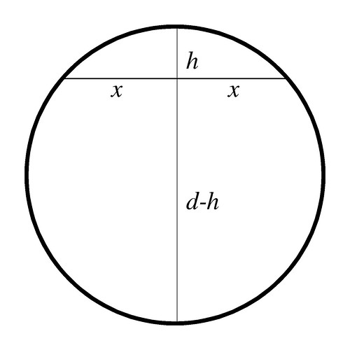
Finally, there is the matter of longer inter city vehicles. Due to overthrow, the width of a vehicle longer than 20 metres must be reduced by an amount proportional to the square of the distance between bogie centres. This is based on the formula x squared equals h*(d-h), where x is half the length of a chord and d is the diameter. h is the distance cut off by the chord. (diagram below)
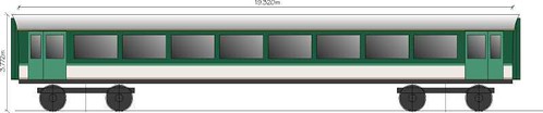
A vehicle 20 metres long can be built to the full permitted width of 2.82 metres. Based on a track curvature of 160 metres, a 23 metre vehicle must be 8 cm narrower (2.74), which is the same width as a mark 1 vehicle due to the projection of door handles etc. A vehicle 21.3 metres, however, loses just 3 cm from the width, whilst gaining an extra bay compared with a mark 1 coach.
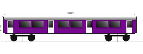
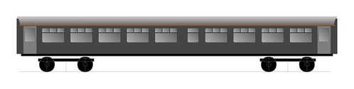
This appears to provide an optimum length, with 9 x bays of 1.9 metres, two vestibules and a reasonable toilet. Such a vehicle is shown below. The upper illustration depicts a historic livery, perhaps because such vehicles might be used for charter work. For the same reason it is shown with sliding ventilators to avoid the need for a power supply for air conditioning, though the photograph as at the bottom give a better idea of what is envisaged. Also of note in this diagram are the toilet compartments in the centre of the vehicle. The main purpose is to simplify plumbing to the sewage retention tank, but it also divides the vehicle into two convenient sized compartments of four and five bays. The end vestibules are slightly larger than customary, with wide doors.
The same dimensions would of course apply to a vehicle fitted with sealed windows and air conditioning and internally would then closely resemble the Alstom Adelante (lower picture). Similar vehicles might well be an appropriate choice for locomotive hauled or electric multiple unit inter-city trains, such as we are likely to see if the IEP project is abandoned.
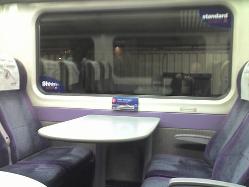
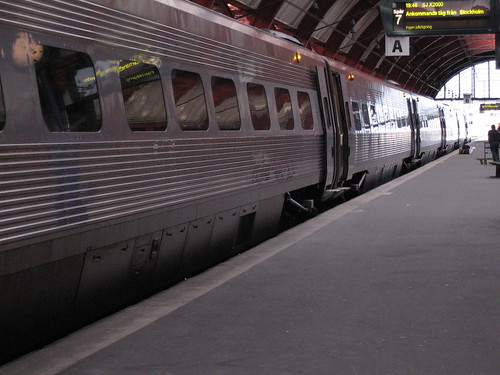
The choice of 1.9 metres for the bay dimension provides a good compromise between comfort and capacity; the vehicle shown could be fitted with 72 seats all correctly aligned to windows, with luggage space between seat backs. A first class version would have 54 seats in a 2+1 configuration on either side of the gangway. 1.9 metres is the bay dimension of the Adelante (below), which gives a good idea of the level of comfort that could be provided in such a vehicle. Were this envisaged, stainless steel bodyshells (bottom picture) would be worth considering on account of their extreme long life and low maintenance requirements.
Wheelchair access
Wheelchair access toilets have to date not been particularly well integrated into the vehicle interior layout. One issue is that the size of the module does not fit with a centre aisle seating layout. Another is that there is a need to provide access to toilets from the entrance vestibule rather than from the passenger saloon to prevent annoyance from bad odours. With this in mind, it is worth considering if wheelchair access toilets should not be associated with other facilities which require an off-centre gangway, such as catering areas, first class compartments and luggage/cycle areas. It would also be worth considering whether toilets should be provided in every vehicle. It might be advantageous to concentrate toilet facilities in fewer vehicles, to avoid the need for plumbing in every coach; this may create the opportunity to offer additional facilities such as showers for passengers' use.
The first of these is what is known as the static loading gauge. This can be thought of as the aperture through which all railway vehicles must be able to pass when running slowly on straight track. In practice, tracks are curved and railway vehicles cut across and project beyond the chord of a circle. Within the wheelbase, the distance cut across the curve is sometimes known as the overthrow and the projection beyond the wheelbase is referred to as the kick-out. A long vehicle cuts off more of a chord than a short one (diagram below) Taking curvature into consideration in this way leads to the concept of the dynamic loading gauge, which, however, also takes account of the suspension characteristics of the vehicle.
The diagram shows how gaps between the platform and the train will arise differently at concave and convex platform faces, and that these gaps can be minimised by keeping doorways as close as possible to bogie centres.
Following the nationalisation of Britain's railways in 1948, a survey of the infrastructure was made and an optimum loading gauge established for passenger vehicles. This was known as the C1 loading gauge and eventually it became possible for vehicles built to this gauge to operate over almost the entire system. The C1 loading gauge applied to vehicles of a nominal 20 metre width with bogies at 14.174 metre centres, of which the first were the Mark 1 fleet.
These (above) were characterised by curved bodysides with the width reducing to cantrail level (where the roof joins the bodyside)
Vehicles to a similar length are still being built, but all of them have two pairs of bi-parting doors at the 1:3/2:3 position. (below)
This divides the vehicle into three saloons, one of four bays in the middle and two of two bays at each end. This is not a particularly satisfactory arrangement. If the vehicle is a monocoque construction, then the large door apertures break into the structure at the worst possible place from the point of view of integrity. Substantial reinforcement is then required around these openings. The second drawback is that the division into three saloons imposes limitations on the alternative seat layouts that can be fitted, because the small end compartments can only be used for four rows of seats (or three and a driver's cab) or some special purposes such as a wheelchair and toilet area. The third drawback is that having just two sets of doors per vehicle leads to passengers bunching round doors at stations, which extends station dwell times. The fourth drawback is that it would be inconvenient to fit internal vestibule doors, so that passengers sitting inside are exposed to cold air in the winter when the doors are open, and there is a heavy load on the heating and ventilation system during hot and cold weather.
What are the alternatives? 20 metre long vehicles are used for two types of service. One is for long distance commuting, for example, South Coast inter city. For such routes, an end-door configuration would be more suitable, provided that attention was paid to the detailed design of the doorway (see previous article), and sufficient vestibule and circulation space was provided to prevent station dwell time from being unduly extended.
The diagram shows a ten bay vehicle, of which the two end bays are vestibules with wide doorways. It would have internal doors between vestibule and saloon, with the aim of improving passenger comfort and reducing the work required of the heating and ventilation system. Such a configuration would not be suitable for rush hour congestion and an alternative with four single doors would be. Having four doors instead of the standard 1:3/2:3 double-door configuration ought to reduce station dwell time. This is shown below. Each vestibule would occupy a full bay and be provided with space for luggage and perch-type seating. Such a train would be suitable for the inner sections of Thameslink and probably Crossrail also.
If higher traffic densities are to be handled, then trains need to have either three or more sets of double doors or two sets of double doors and single doorways at each end, the standard on tube LUL stock.
Inter city vehicles
Finally, there is the matter of longer inter city vehicles. Due to overthrow, the width of a vehicle longer than 20 metres must be reduced by an amount proportional to the square of the distance between bogie centres. This is based on the formula x squared equals h*(d-h), where x is half the length of a chord and d is the diameter. h is the distance cut off by the chord. (diagram below)
A vehicle 20 metres long can be built to the full permitted width of 2.82 metres. Based on a track curvature of 160 metres, a 23 metre vehicle must be 8 cm narrower (2.74), which is the same width as a mark 1 vehicle due to the projection of door handles etc. A vehicle 21.3 metres, however, loses just 3 cm from the width, whilst gaining an extra bay compared with a mark 1 coach.
This appears to provide an optimum length, with 9 x bays of 1.9 metres, two vestibules and a reasonable toilet. Such a vehicle is shown below. The upper illustration depicts a historic livery, perhaps because such vehicles might be used for charter work. For the same reason it is shown with sliding ventilators to avoid the need for a power supply for air conditioning, though the photograph as at the bottom give a better idea of what is envisaged. Also of note in this diagram are the toilet compartments in the centre of the vehicle. The main purpose is to simplify plumbing to the sewage retention tank, but it also divides the vehicle into two convenient sized compartments of four and five bays. The end vestibules are slightly larger than customary, with wide doors.
The same dimensions would of course apply to a vehicle fitted with sealed windows and air conditioning and internally would then closely resemble the Alstom Adelante (lower picture). Similar vehicles might well be an appropriate choice for locomotive hauled or electric multiple unit inter-city trains, such as we are likely to see if the IEP project is abandoned.
The choice of 1.9 metres for the bay dimension provides a good compromise between comfort and capacity; the vehicle shown could be fitted with 72 seats all correctly aligned to windows, with luggage space between seat backs. A first class version would have 54 seats in a 2+1 configuration on either side of the gangway. 1.9 metres is the bay dimension of the Adelante (below), which gives a good idea of the level of comfort that could be provided in such a vehicle. Were this envisaged, stainless steel bodyshells (bottom picture) would be worth considering on account of their extreme long life and low maintenance requirements.
Wheelchair access
Wheelchair access toilets have to date not been particularly well integrated into the vehicle interior layout. One issue is that the size of the module does not fit with a centre aisle seating layout. Another is that there is a need to provide access to toilets from the entrance vestibule rather than from the passenger saloon to prevent annoyance from bad odours. With this in mind, it is worth considering if wheelchair access toilets should not be associated with other facilities which require an off-centre gangway, such as catering areas, first class compartments and luggage/cycle areas. It would also be worth considering whether toilets should be provided in every vehicle. It might be advantageous to concentrate toilet facilities in fewer vehicles, to avoid the need for plumbing in every coach; this may create the opportunity to offer additional facilities such as showers for passengers' use.
Kommentarer